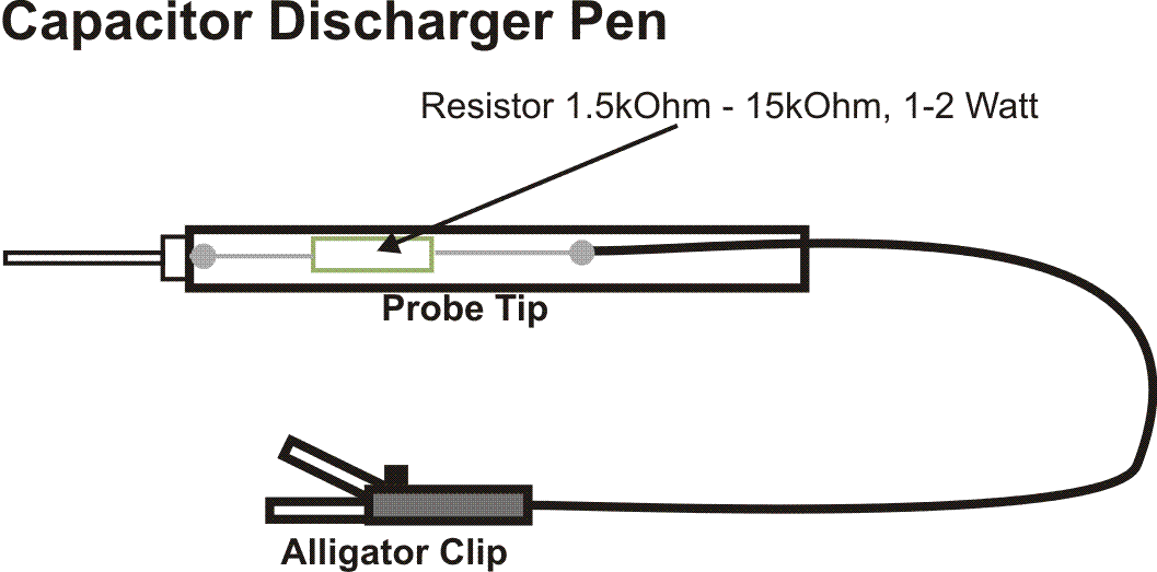
This tool is used to discharge the capacitors in the power-supply. The alligator clip is clamped to the chassis while the probe-tip is held against the (+)-contacts of the capacitors for a few seconds. This discharges the capacitors and reduces the risk of electric shock for you. Always disconnect the amplifier completely from mains power before you start your work.
The probe tip has to be isolated for at least 1000VDC.
The PE-connection (Protective Earth) has to be designed as a discrete connection by using a screw, a toothed washer and a safety nut as well as a label carrying the PE-sign. To connect the wire (coloured green/yellow) crimp jacks are perfect, but soldering is also a good choice. This connection is further connected to the Star-Ground.
You may NOT use any other screw that is fixing another part of the amp (e.g. transformer) to accomplish the PE-connection.
Important: All touchable metal parts of the chassis need to have a solid PE-connection!
Tips and more about building amplifiers
All ground-wires should be consolidated in one Star-Ground point.
From Star-Ground one wire goes to the PE-connector.
CHASSIS
Star-Ground
PE-Connection (Protective Earth)
Click to enlarge.
Click to enlarge.
Discharger for electrolytic capacitors
More Tips
Always drill wires carrying AC. This will avoid hum caused by emitted electromagnetic fields from the wires. Due to the drill the electric fields kill themselves.
This applies to all AC carrying wires e.g. from the power-transformer to the rectifier or from the power-transformer to the heaters of the tubes and the control lamp.
Because the wires to the heaters reach far into the chassis you should always keep them apart from other wires especially those carrying the audio signal.
The mains cable should also be drilled inside the chassis. This only applies for L1 (black) an N (blue), but not to PE.
The PE-cable (Protective Earth) has to be lead to the PE chassis connection so that it will always be the last wire to tear off if heavy pull is performed to the power cable. Forming a slope is a good choice.
Use shielded wires for the signal-cables (especially between the input jacks and first amplifier stage. The shields are connected to chassis ground only at one side (usually the lower impedance side - usually the preceding amplifier stage output or the input jacks). This will avoid hum influence to the signal wire.
Place input jacks and preamp tubes as far as possible away from the power transformer.
Use isolated washers to separate input jacks from the chassis and connect the jack’s input ground signal directly to the star-ground using a separate wire.
Power transformer (PT) and output transformer (OT) have to be twisted against each other by 90°. This is to avoid hum transmission from the PT’s magnetic field into the OT’s windings.
Tube Amp Power Supply and Protection of Components.
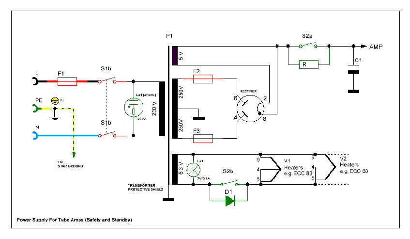
The picture above shows a typical tube amp power supply. I have marked important or optional parts, which do improve safety or support the economical handling of the amp. Parts supporting safety are marked in red and optional parts are marked in green color. Safety in this case is related to humans as well as to the amp’s parts themselves.
Mains-fuse and On/Off-Switch
The mains-fuse (F1) has always to be placed before the mains switch (S1a+b) to absorb all possible defects of the amp. In the event of a failure the fuse will blow and cut the amplifier from the power. The mains-switch has to be a double-pole switch handling both electrical poles (L and N) to insure a save cut-off of the power, independently from the position/orientation of the mains plug in the wall-outlet.
Please keep in mind that the load capacitors inside the amplifier will still keep the full DC-voltage for a while. Therefore better use a discharging tool to get the capacitors savely discharged (see above!) before starting any maintenance activity.
Fuse on the secondary side of the PT
At some older amps (like those I have built after the originals) you may recognize a fuse placed in the center tab of the secondary high tension winding and chassis ground. With our up-to-date knowledge this is no longer the best choice, because if the fuse blows off there will remain a hazardous voltage at the rectifier tube. In the example above this means deadly 500VDC! Zwo fuses (F2 and F3) placed in the outer tabs provide a much better protection.
Standby
In order to extend the tubes lifes it is recommended to heat the tubes first before applying high voltage. This is performed by the standby switch (S2a in the picture), which is available in most tube amps. The optional parallel resistor (R) disburdens the tubes and the fuses when high voltage is switched on, because it constantly lets a very low current pass through, which will avoid a shock reaction from some critical components. Due to this resistor the amp will no longer be totally quiet in standby-mode, because of the remaining low current (2-4mA) still floating through the resistor, but which is low enough to be ignored. A good choice for this resistor is 56kOhm 2-3Watt.
Observe: Standby-mode is only to be used in case you stop playing for a little while (appr. 10-15min). Longer use of this mode may harm the tubes again (cathode poisoning).
In case you have a double-pole switch available for the standby function you may use the variant with S2b and the diode (D1) in the heating circuit of the tubes. By means of the diode one half-wave of the current will be cut, which reduces the heating power delivered to the tubes during standby. This will further extend the live of the tubes.
Power Control (Pilot-Lamp)
The power control may be a 230V neon bulb attached to the primary side of the power transformer or a 7V/300mA filament lamp on the secondary side in the 6.3V circuit for the heaters. The latter you will find in most Fender amplifiers.
I recognized that many of the 7V 300mA pilot bulbs available today die after a too short period, although the transformer is delivering ~6.3VAC only. This also can’t be caused by the usually higher voltage in our supply networks today (230VAC rather than 220VAC), because this is compensated by setting the input voltage switch to 240VAC (at least in Europe). Could it be a general quality issue?
But putting a resistor of about 270 Ohms 3 Watt in series will extend the bulb’s live significantly.
!!! Protection Earth (PE)
From the mains connection socket or the cable entry (of course with pull relief and/or bend protection) the PE-connection is made by means of a separate screw joint firmly to the chassis. The contact resistance should not exceed a few milli-ohm (10-³ Ohm). If the chassis is painted remove the paint at the position of the screw to insure optimal contact. A lock washer has to be placed between the contact tab and to be fixed by a double nut or a lock nut to assuree a permanent fit. The PE-wire coming into the chassis shall enough lengh, that in case of unexpected pull this connection will break at last, so that the PE-connection is assured as long as possible. If this wire breaks before the other two it may happen that the hot wire (L) touches the chassis and mains voltage is lead to your guitar or the microphone in your hands. The possible result you may imagine yourself!
If you intend to build your own amp or you want to perform a repair job, you should consider some safety rules, which are key to a good working amplifier and for your health as well. This especially applies to vintage amps, which have been built under former safety recommendations, which do not longer fit to up-to-date requirements. The following recommendations - especially those related to electrical safety - should be imperatively considered in order to save your and other peoples lives.
Miscellaneous
Against hum and additional safety


|
|
(c) 2011 Dipl.-Ing. B. Brieskorn